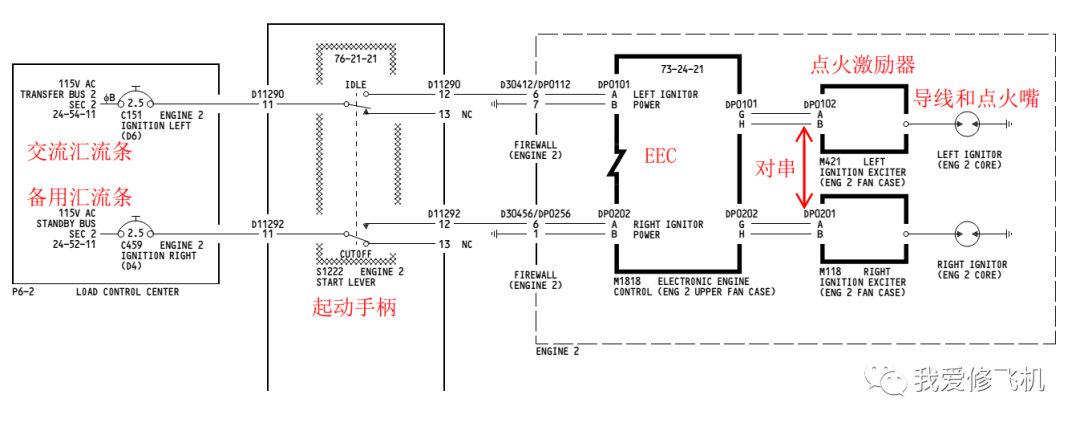
保留程序针对未安装 R913/R914 电源感应继电器的飞机构型,目前机队均为这种构型。此程序将左点火激励器连接到交流备用汇流条,以右发为例,MEL74-01-02-02B。This task connects the left igniter to the AC STANDBY BUS.
D 4 C00459 ENGINE 2 IGNITION RIGHT
D 6 C00151 ENGINE 2 IGNITION LEFT
2. 确认发动机起动手柄在CUTOFF位,并挂红牌。4. 打开相应发动机的右风扇包皮,若是左发请先完成前缘限制程序。5. 脱开左右点火激励器的供电线缆。电插头安装位置见下图。6. 对串左右点火激励器的供电线缆。完成操作后的电插头位置见下图:7. 拆除发动机的左右点火跳开关上的红牌,并闭合跳开关。8. 拆除发动机启动手柄和启动电门上的红牌,确认起动手柄在CUTOFF位,起动电门在OFF位。9. 视情进行发动机干冷转,以清除发动机内部剩余的燃油。确认尾喷管下部无燃油。10. 使用飞机勤务内话,确保驾驶舱人员实时与地面人员保持联络。地面人员应该使用轮舱处耳机插孔。11. 接近P6-3面板拔出发动机的燃油翼粱活门跳开关并挂红牌:B 3 C00360 FUEL SPAR VALVE ENG 2
12. 驾驶舱人员接近FMCS CDU,并按照以下步骤进入发动机点火测试页面。先按INIT REF键,进入下图界面。然后按照提示顺序按压行选键。13. 分别进行左右点火测试。要求右点火测试必须通过,即:无故障代码,地面人员听声正常。而左点火测试可以不通过。若右点火测试不通过,飞机不能放行。It is permitted to find faults with the left ignition system, but the right ignition system must
pass the audible test.
NOTE: When the EEC tests the right ignition system, the left igniter will fire because of the wiring change. This audible check means the right ignition system is correct.
通知地面人员注意听点火声音,在CDU键盘上输入OK,并按压CONTINUE键。地面人员确定能听到时间长度为10秒的持续点火声。此时点火为EEC的A通道进行测试。地面人员确认再次响起点火声音,声音持续10秒。此时为B通道进行的点火测试。注意:驾驶舱测试完成后,显示无点火故障,并且地面人员听到有时间间隔的两段点火声音,那么测试正常。结束测试,按压以下行选键14. 按压INIT REF键,退出发动机自检界面。16. 拆除发动机燃油翼粱活门跳开关上的红牌,并闭合跳开关17. 在点火选择电门处标注——“只能用双点火”。并告知机组,使用右点火起动后发动机后,将点火起动电门选择在BOTH(双点火)位。
右发保留M项是为了将交流备用汇流条给正常的点火系统供电,正常的点火系统必须从备用汇流条供电,以免飞机意外掉电时发动机无法点火。跳线只是对EEC下游部件进行,此时交流备用汇流条接的还是右点火线路,所以保留(M)项完成后的测试是针对右点火系统进行的,而左点火系统此时是故障的。
注:737NG右点火系统部件失效,只有当点火激励器,点火导线或者点火嘴中的一个或多个失效是能保留,其他部件(点火激励器上游)失效是不能保留的。
若点火系统安装了 R913/R914 电源感应继电器( AMM 74-00-00/901 )。
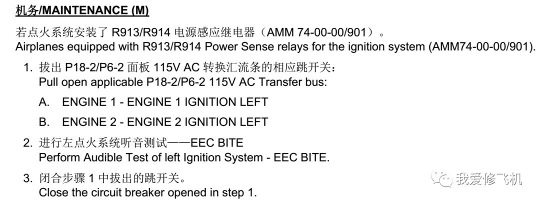
机队目前没有这种构型的飞机,所以不需要按照这个内容操作。若点火系统未安装 R913/R914 电源感应继电器。将左点火器连接到 AC 备用汇流条上( AMM 74-00-00/901 )。
2、点火系统安装 R913/R914 电源感应继电器,目的是确保交流汇流条没有电时,左点火系统从备用交流汇流条得电。如果飞机安装了 R913/R914 电源感应继电器,右点火失效保留就不需要跳线了,只需测试确保左点火能从备用汇流条供电即可,保留程序将变得很简单。
3,相关R913/R914 电源感应继电器资料如下。
REFERENCES:
/A/ GUN-GUN-18-0283-01C
DESCRIPTION:
In the (M) procedure of MMEL 74-01-02-02B of Boeing 737 DDG, Boeing lists two configuration, one is for airplanes equipped with R913/R914 power sense relays, the other is for airplanes not equipped with those. And we don't find any information about the relays in CSN's AMM/WDM/SSM.
DESIRED ACTION:
Q1: Without any information about the relays to be found, whether does it mean that CSN is not equipped with the R913/914 power sense relays ?
Q2: Please provide us with some information or background about the R913/R914,such as the SB/STC or their function, for the relays may be evaluated whether to be installed in the future.
RESPONSE:
Answer 1: The R913 and R914 Power Sensing Relays are not installed on any China Southern Airlines 737NG airplanes. If installed, the relays would be found in the J24 junction box and illustrated in the System Schematic Manual (SSM) and Wiring Diagram Manual (WDM) in Section 74-11-11.
Answer 2: There is no service bulletin installation available to retrofit airplanes with these relays. This installation has only been offered as an option to operators of new airplanes. For 737NG airplanes, the Left Igniter is connected to 115VAC Transfer Bus and the Right Igniter is connected to 115VAC Standby Bus in normal configuration. The installation of Power Sensing Relays R913 and R914 ensures that the Left Igniter is powered by the 115VAC Standby Bus when 115VAC Transfer Bus is not available. yibiao
 kingair
 s0
s0
 粤公网安备 44040302000324号
粤ICP备15064906号 Powered by Xuefeiji X1.0 Code ©2003-2020
粤公网安备 44040302000324号
粤ICP备15064906号 Powered by Xuefeiji X1.0 Code ©2003-2020