 yibiao
 kingair
 s0
s0
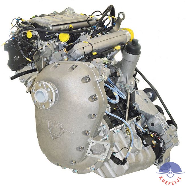
AE300 E4 Engine series Scheduled Maintenance Checks
The scheduled annual inspection consists of the 100 hours inspection program.
Activities/Service Interval | 100 h | 300 h | |
General | |||
0. | Send the following data to Austro Engine GmbH: – Serial Number of the Engine(s) – Serial Number of the Aircraft – Aircraft Registration Marks – Company |
X |
X |
1. | Review the applicable Airworthiness Directives. | X | X |
2. | Review the applicable Service Bulletins. | X | X |
3. | Review the Life-Limited Parts list. Refer to Section 05-10-00. | X | X |
4. | Review the Component Maintenance Requirements. | X | X |
5. | Visually examine the whole engine surface using a flashlight and a mirror. – Look especially for signs of wear and leakage at the oil sump gasket and the cylinder head gasket. – Examine for loose parts or foreign objects. |
X |
X |
ELECTRIC | |||
6. | Examine the glow plug control. Refer to Section 80-00-00. | X | X |
7. | Examine the Alternator according to Chapter 24-00-00. | X | |
8. | Visually examine the wiring harness for signs of wear or damage. - Make sure that the camshaft sensor connection and the injector connections are tight fitted. |
X | |
9. | Visually examine the wiring harness that is not covered by the injector cover for signs of wear or damage. Make sure that the sensor connections are fitted tight. CAUTION: To prevent any damage on cables and sensor, do not put too much force on cables! |
X |
X |
10. | Read out EECU using the AE 300 Wizard. Send the following data to Austro Engine GmbH: – Engine log - Event recorder - Engine data log |
X |
X |
11. | Examine the fault code memory of the EECU for failure. Refer to Section 76-10-00. |
X |
X |
GEARBOX | |||
12. | Visually examine the Gearbox. Look for leakages at the housing and propeller shaft. |
X |
X |
13. | Measure the Gearbox Oil level according to Section 12-10-00. | X | X |
Activities/Service Interval | 100 h | 300 h | |
14. | Drain the Gearbox Oil according to Section 85-10-00. | X | X |
15. | Examine the Gearbox Oil according to Section 85-10-00. | X | X |
16. | Collect a sample of used Gearbox Oil using the oil container provided with the 300 h Service Kit. - Send the oil sample to oil check directly (pre-filled out envelope). |
X | |
17. | Examine the Gearbox Oil Filter according to Section 85-10-00. | X | X |
18. | Replace the Gearbox Oil Filter according to Section 85-10-00. | X | |
19. | Refill the Gearbox Oil according to Section 85-10-00. | X | X |
BELT DRIVE SYSTEM | |||
20. | Visually examine the V-Ribbed Belt. Look especially for abrasion and signs of damage: - Textile reinforcement visible between the ribs - Tapered ribs - Transverse cracks on the running surface - Dirt between the ribs - Transverse cracks in the ribs - Frayed textile reinforcement. In case of dirt clean the V-Ribbed Belt using water only. |
X |
X |
21. | Examine the belt pulley profiles and the tensioner for damage and dirt. | X | X |
ENGINE OIL | |||
22. | Drain the Engine Oil according to Section 79-20-00 Paragraph 5.A. | X | X |
23. | Collect a sample of the used Engine Oil using the oil container provided with the 100 h Service Kit. – Send the oil sample to oil check directly (pre-filled out envelope). |
X |
X |
24. | Replace the Engine Oil Filter according to Section 79-20-00 Paragraph 3. | X | X |
25. | Visually examine the used Oil Filter for contamination and metal abrasion. – If an abnormal condition is found (metal shavings exceeding 1.5 mm; concentration of particles; clogged filter), this condition must be corrected (e.g. by exchange of defective component within published repair procedures) before further operation of the engine. |
X |
X |
26. | Fill the Engine Oil according to Section 79-20-00 Paragraph 5.B. | X | X |
FUEL SYSTEM | |||
27. | Visually examine the Fuel System for signs of wear and leakage. Make sure that the fittings are tightened. |
X |
X |
28. | Replace the Fuel Filter in accordance with the applicable Aircraft Maintenance Manual. | X | X |
Activities/Service Interval | 100 h | 300 h | |
COOLING SYSTEM | |||
29. | Visually examine the Cooling System. - Look especially for signs of wear and leakage. - Make sure that the connections are tight fitted and the hoses are not damaged. |
X |
X |
OIL SEPARATOR | |||
30. | Examine the outlet of the Breather Line for abnormal quantity of oil (oil dust has to be expected). - In case of oil detection, clean the Breather Outlet and do an engine ground run according to Section 71-00-01. - After the ground run examine the breather outlet again for obvious oil accumulation. - Examine and replace the breather line according to the applicable Aircraft Maintenance Manual. |
X |
X |
ENGINE | |||
31. | Disconnect Cylinder Head Drain Line from cylinder head below the high pressure fuel pump. Carefully blow compressed air through the drain hole. Blow compressed air through the Cylinder Head Drain Line to make sure that the line is not clogged. Connect the Drain Line. |
X |
X |
32. | Remove the Injector Cover according to Section 85-10-00 Paragraph 3.A. | X | |
33. | Visually examine the high pressure fuel lines for signs of wear, leakage and poor condition. | X | |
34. | Visually examine the Injectors for: – fuel/oil leakage at injectors attachment – fuel leakage at common rail – fuel leakage at fuel return line Do a check of the nuts torque at common rail side. Do a check of the nuts torque at fuel line. Refer to Chapter 73 for torque values. NOTE: Any leakage must be documented and reported to Austro Engine GmbH. |
X | |
35. | Examine the Oil Separator hoses for damage. | X | |
36. | Examine the Oil Separator for signs of leakage. | X | |
37. | Visually examine for coolant loss at the cylinder head. | X | |
38. | Clean the area below the injector cover using cleaning agent. Make sure that the cylinder head drain is not clogged: The cleaning agent must drain off through the cylinder head drain line. - Do not apply cleaning agent on opened sensor connections. |
X |
Activities/Service Interval | 100 h | 300 h | |
39. | Install the Injector Cover according to Section 85-10-00 Paragraph 3.B. | X | |
EXHAUST SYSTEM | |||
40. | Visually examine the Wastegate Controller for: - Deformations at the connection rod - A deformed mounting eyelet at the rod eye of the waste gate - Mechanical fractures/dents/chafing marks/cracks (affecting the functionality). |
X |
X |
41. | Examine the Wastegate Controller bridge for: - Loose clamps or cable - Broken or frayed wires - Excessive wear |
X |
X |
42. | Examine the pressure setting of the Wastegate Controller according to Section 81-20-00 Paragraph 5.C. | X | X |
43. | Examine the exhaust manifold for cracks using a flashlight and a mirror. | X | X |
44. | Examine the exhaust manifold gaskets for signs of leakage. | X | X |
45. | Remove the intake air hose from the turbocharger according to the Airplane Maintenance Manual. | X | X |
46. | Visually examine the Turbocharger for: - Oil leakage - Mechanical wear and damages at the compressor blades - Significant wear and grooves at the air intake - Damage concerning functionality of the turbocharger and sealing (e.g. sealing surfaces…) |
X |
X |
47. | Examine the torque seal indicator (backplate to bearing housing) at the turbocharger. Make sure that the torque seals are not broken. Refer to Fig. 81-4. |
X |
X |
48. | Examine the aircraft oil consumption. The accumulated oil consumption according to the Logs must not exceed 0.1 l/h. |
X |
X |
49. | Install the intake air hose according to the Airplane Maintenance Manual. | X | X |
50. | Renew the torque seal. Refer to Fig. 81-4. - Carefully remove the torque seals. - Clean the surface. The surface at the torque seal positions on the turbocharger must be free from residue. - Do not use degreasing agents! Do not scrape with sharp tools on the turbocharger parts! - Apply the torques seal (Bäder Lacke Schrauben-Sicherungslack, color blue) on the cleaned surface at the turbocharger. The torque seal must cover the compressor and the bearing housing. |
X |
X |
Activities/Service Interval | 100 h | 300 h | |
51. | Complete an engine ground run according to Section 71-00-01. | X | X |
52. | Examine the oil system for leakage. - If leaks are found, examine the root cause and do the repair procedures as published within this maintenance manual. - Measure the Engine oil level according to Section 12-10-00. |
X |
X |
53. | Complete the maintenance log and put it in the Engine Maintenance Log. | X | X |
 粤公网安备 44040302000324号
粤ICP备15064906号 Powered by Xuefeiji X1.0 Code ©2003-2020
粤公网安备 44040302000324号
粤ICP备15064906号 Powered by Xuefeiji X1.0 Code ©2003-2020